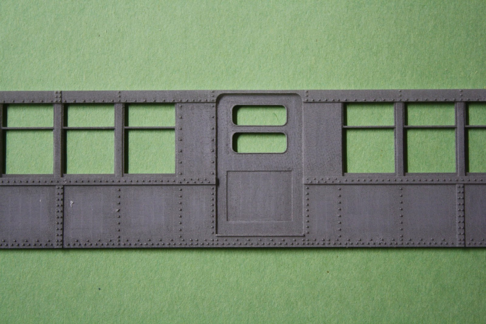
Below are some of the baldie samples placed loosely together.
The side does have some warp-age to it, but that could be corrected by internal bracing.
My original plan was to make molds of the sides and then cast the sides out of resin.
Well, that didn't work out too well. I tried to make a mold out of one of the sides, and I didn't prime the side beforehand nor did I add mold release. BIG MISTAKE as seen by the below "after" pictures of what was left of the side:
As you can see, the silicone rubber stuck to the part and basically broke it when I tried to remove the side from the material.
I was able to successfully make a mold out of the side shown at the top of the page. However, I haven't really been too happy with the quality of the castings I've been getting. I think for a model, just working directly from the prints is preferable.
My Met L structure turned out very well. However, I realized that copying directly from prototype plans was a mistake. The center line of the track girders on the prototype is 5 feet. With O standard being 5 feet, I thought it wouldn't be an issue in replicating the measurement in the model.
As can be seen in the below photo, the O standard gauge, while 5 feet, puts the center line of the rail on the outer edges of where the girder would be. The flat areas on the cross girder are where the long, horizontal girders would be.
The girder center lines should fall directly under the center line of the rail, NOT the gauge.
I will need to redraw the model and resend for printing. The difference isn't large, but if going through the trouble of making the lattice style, the girder / rail spacing needs to be correct.
The model I have is correct for proto48 track, but not standard O gauge (5' gauge track).
I've also made progress on my newer, more detailed structure. This L structure is a combination of cast girders, styrene shapes and 3D printed (then cast out of resin) corner braces.
I've tried to add as much rivet detail as I can to the various components. The column height is a little taller than I'd prefer, but that was dictated by the benchwork in this area of the layout. The track obviously needs to stay level with the rest of the layout, which dictates the column height.


I'm following your progress with great interest as I am planning on going this route but in HO scale. Not sure how you are making your molds but FUD and FD usually work very well as masters. Sealing the masters and mold release is absolutely necessary. Aside from that, you should be gluing the masters to a flat back (or perhaps designing the flat pieces with an integral backing though you would be using more material and incurring additional costs) which will help with the warping when you actually go to casting.
ReplyDeleteBest of luck.
3D modeling means the mathematical representation of the surface of an object. The 3D model will allow you to see the 3D visualization of your project before starting the construction. Onsite3D can provide you the best 3D modeling service in Calgary. 3D model Calgary, Alberta
ReplyDelete