Tuesday, December 27, 2011

Building L structure, part four - connections

All of my structure is built in modules. Each module connects to the next using a nut and bolt.

I try to keep each section of structure approx. three feet in length. Any longer and the sections become more difficult to assemble.

The connection is made by having one of the cross girders be .040" styrene while the next cross girder is MDF. The L section with the end cross girder of .040" styrene "slots' in next to the girder made out of MDF. Before attaching the other girders, I drill a hole in the two girders. I can then insert a nut and bolt to connect the two sections.

The below photos illustrate this modular connection.


This is a connection between a two track straight section and a the begining of the island station. The track to the right curves to the right to clear the island station. The grey MDF cross girder can be seen along with the .040" cross girder of the unpainted section. A nut and bolt holds the two sections together.


This picture shows the reverse side of the above connection. The unpainted girders have been glued to the .040" styrene cross girder using super glue. Reinforcing angles will be added later. For the angled sections, .010" styrene will be cut into squares, bent to match the angle, and used as reinforcement.


Here is another picture of the connection. In this picture there are three sections of L structure. One in the foreground, one in the middle consisting of two girder spans and one in the background (the bolt is visible in the background).


I've found that this modular system works best as it allows the various sections to be built seperately and more easily. In addition, I can then remove sections from the layout as needed when working on the underlying scenery.

None of my structure is attached to my benchwork. The structure sits loosely on the "stone" foundations I make out of 1 / 4" MDF. Once the positions of the columns are determined, only those foundations are glued to the benchwork.

Monday, December 26, 2011

Focus Stacking

Even though I use a DSLR to take pictures, I still don't get the depth of field I like.

So, I've been experimenting with a program called Helicon Focus to do what is called focus stacking. You take a series of photos with different focuses, and the program combines them to give a greater sense of depth.


Some examples, each is made up of four pictures.


The program was $30 for a one year license, which is a lot cheaper than a new lens. 


I've also added some dummy streetlights to my street. Painted the typical Chicago green. I'm also trying to figure out a way to add trash/garbage to my street scene. I haven't found a good solution yet.

Saturday, December 24, 2011

Merry Christmas and safe travels to all

Merry Christmas to all and safe travels.


Waiting for the train to take me to the Christmas party. Weather is very mild in Chicago this year!

Friday, December 23, 2011

How to build L structure, part 3 - straight track

The following is how I build straight sections of structure...laying out the girders.

Each section is built in approx. three foot sections. The sections are linked together using nuts and bolts. I'll cover the exact method in a later post.

The first step is to lay out the track. The brand of track you use will dictate your track spacing. I am using Gargraves track.

In this case I am building a stub end terminal. The track on the right jogs to the right to make room for an island platform.

The stub end siding on the left is for storage.

Note - I haven't laid out any streets yet. Just the track.

My streets are made out of 1 / 4" Masonite ... from the same 2 x 4 sheets that would be used to make backdrops. Don't lay out any streets yet. Build/plan the track on the flat benchwork.


The next step is to cut the long girders. For mine, I make them 12 " (48 scale feet) long. Once cut, I add the vertical stiffeners.

By laying out the girders, you can determine where the columns will be. This helps when planning where streets will go (if they are cross streets) or where stations will go.

Note I was smart enough to pre-paint these girders before assembly. I have since stopped doing this and the structure is a bit more tedious to paint.


With the girders cut, and using the track layout as a guide, you can cut the cross girders and begin assembly.

I assemble the girders on a large, flat surface (an old shelf from a cabinet).

Below is a picture of the girders being assembled:


I cut some wood blocks (seen at the top of the picture) to act as spacers. It speeds construction.


In this picture I have assemble two sections: the three girder span in the foreground and a three girder span in the background. They will be connected by a two girder span in the middle. When building, I check the progress of the structure by placing it on the track to make sure that all the girders line up properly under the running rails.


I haven't yet added any flanges....just connecting the girders.

I use super glue to glue all the pieces together. I don't have the name of the brand I use handy, but I buy it at Hobby Lobby for $4.99. I comes in a green bottle. My next post will have more details as I'll list the tools I use.

To reinforce the joints of the girders, I glue styrene angles to the joints. This adds significant strength to the structure.


Note the joint. I've added a piece of styrene angle to reinforce the joint. I added angles to each side of the girder. I strongly recommend adding these angles as it really strengthens the structure.

In the above picture you can also see some the added detail of vertical stiffeners on the girders. In these shots you can see it is just strip styrene (.030" x .080"). I have since switched to .080" angle as the angle is a lot easier to glue on.

My layout is a shelf style layout, so the structure can only be seen from one side. Therefore, I cheated and detailed only one side of the structure with the vertical stiffeners since you can't see the back side .... laziness on my part.

My next post will cover how I connect all the sections together and add some flanges to the girders. Where you decide to place your columns will dictate how you place your flanges so I'll cover that in a later post.

Note also that I haven't yet attached any columns. That will be covered in a later post also. The height of the columns depends on your eventual scenery plans and I'll show some of the considerations to take into account when planning that.


O Scale Cabrini Green Housing Projects

One iconic / infamous set of buildings on Chicago's near north side were the Cabrini Green housing projects. The Ravenswood ran along side the projects and the projects were featured in the opening credits to the TV's hit TV show "Good Times".

With this, I felt I had to have at least one of the classic Cabrini Green projects on my layout. It is a part of Chicago's history ... since they have been torn down.

The original:


My version, still under construction, is made of 1 / 4" MDF (very versatile!) covered in paper. The building images were made using Evan's Designs Model Maker building with textures obtained from cgtextures.com.


Model Builder isn't the best program, but it gets the job done. Eventually I will add a recessed entry way (the large hole at the base), some additional textures for molding around the top and add some scenery around the base. In front of the L tracks I plan on putting an urban park consisting of a basketball court.

Examples of different MDF Thickness

As mentioned in the materials post, I have switched from using Home Depot 1 / 4" thick MDF to 1 / 8" thick MDF. 

The below section was built with  1 / 8" MDF:


This section was build with 1 / 4" MDF:


Not a gigantic difference, but the 1 / 8" is a little less beefy. I haven't noticed a significant lack of strength with the 1 / 8" structure.

How to build L structure, part 2 - Materials

Materials list:
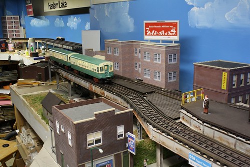
The structure is a combination of MDF, basswood and styrene. The girders are MDF, the columns and girder flanges and basswood and the details are styrene.
I chose MDF for the girders as I found it to be the most economical material as compared to styrene or basswood. It is easily found in 2 x 4 sheets, inexpensive, glues well and takes paint nicely. However, one large drawback is the amount of dust generated while cutting.
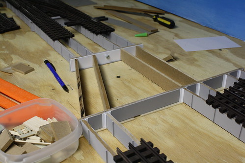
Note – my structure is built out of two types of MDF. 1 / 4“ thick and 1 / 8” thick. The 1 / 4” thick panels are found at Home Depot for approx. $5 for a 2 x 4 sheet. This is what I built the Sheridan Road station and structure out of.  I recently found 1/8” MDF sheets at a specialty lumber yard (Owl Lumber in Chicago). A 4 x 8 sheet was approx. $10. Since I bought two sheets of the 1/8” thick MDF, all currently structure is built out of the 1/8” MDF. The construction methods for the two thicknesses are the same. Just the column size and flanges are modified. I will list materials for both types. The pictures showing construction will be of the structure built with 1/4 “ thick MDF.
Check at a specialty lumber yard for 1 / 8” MDF. It is used for furniture and cabinet making. A big box home improvement store won’t carry it. The effect of using the thinner MDF is nice.
I would not recommend using the 1 / 8” Masonite / hardboard panels that folks use for backdrops. These are the 2 x 4’ panels that are smooth on one side and have a texture on the other. They don’t cut as cleanly as the MDF and the textured side could cause problems.
Either thickness will work. The 1 / 4” is more readily available, the 1 / 8” looks a little less beefy.
List:
Structure built using 1 / 4 “ MDF:
1 / 4 “ MDF – for girders, cut into strips for the girder’s height
1/16 “ x 1/2 “ basswood strip – for girder flanges and column flanges
1 / 4 “ x 1 / 4 “ basswood strip – for columns
.030” x .125” Evergreen Strip part # 125 – for column detail
1 / 4” Evergreen L angle, part # 297 - for girder attachment reinforcement
Structure built using 1 / 8 “ MDF
1 / 8 “ MDF - for girders cut, into strips the the girder’s height
1/16 “ x 3/8” basswood strip – for girder flanges and column flanges
3 / 16” x 3 / 16” basswood strip – for columns
.030” x .100” Evergreen Strip, part # 135 – for column detail
5 / 32” Evergreen L angle, part # 295 - for girder attachment reinforcement
Materials Common for both methods:
                For the vertical stiffeners on the girders – two choices: The using the angles are easier to glue. Using the strips is cheaper.
                .080” Evergreen Styrene L Angle, part #  292 – for vertical stiffeners on girders
                .030” x 0.080” Evergreen Styrene strip, part # 134 – for vertical stiffeners on girders
                .040” Sheet styrene, any brand, for column bases
                1 / 8” x 1 / 8” basswood – for diagonal stiffeners between girders
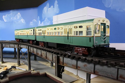
Size of girders:
Your prototype will determine what size girders use will use. For my Chicago prototype, I use a scale 4 feet or 1 inch tall girder. New York structure might be better represented by 5 scale feet or 1.25 inches (both O scale). I cut the MDF into the strips using a base model Craftsman table saw. A table saw is probably the only way to get consistent widths on the girders. The economics of the MDF are apparent as a 2 x 4 foot sheet of MDF will yield a lot of strips to be used as girders.
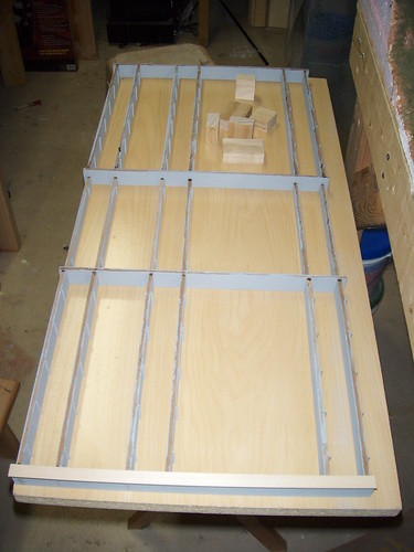
Quantities: Quantities of the materials will depend on how much structure you build. But, I built approx. 8 feet of L out of one 2 x 4 sheet of 1 / 4” MDF. The basswood strips used for the flanges will require a significantly larger amount.

Wednesday, December 21, 2011

MTH 6000's

I have to say MTH did a good job the the CTA 6000's.

Waiting at the Sheridan Road station ...

How to build L structure, part 1

I have based my L structure on the Chicago L prototype. It is designed to be built easily, with minimal cost and sturdy enough to support MTH O Scale subway trains.

When building L structure, you first need to decide on what style you wish to build.


The above graphic shows a couple of different two track styles. Depending on your prototype, additional tracks can be added as needed.

Type A has the columns directly under the centerlines of the tracks. This is a typical style for Chicago's L's that run in alleys as there isn't room for a street underneath.

Type B has the columns spaced at the outer edge of the track. A street can be placed underneath as the columns would sit in the street as on either the Wells or Wabash legs of Chicago's Loop.

Type C has the columns spaced further apart. This would be used for a street, either placing the columns on the sidewalk/curb or in the street.

Whatever you chose, decide on what type you want to build before you start. This way the length of the cross girders can be predetermined.

Welcome to the CTA O Scale Layout Blog

Welcome all to the newly established blog for my O Scale CTA L layout.

Here I will share pictures, methods and knowledge as I slowly build my CTA L layout.


My philosophy for my layout is to keep things as simple, easy to build and inexpensive as possible.