Sunday, December 10, 2017

Continued track work and brick paving

Yikes ... almost six months since my last post. Time flies and all that ...

Anyway, I've been slowly working on my two straight modules that are a good fit for downtown condo living.

First up ... the eventual 90 degree street intersection track work has been completed.


The turnouts are functional, so with a little creative trimming, I could always expand to the left if I so chose to fit in another module. For now, it will just be a scenic detail.

As discussed in prior posts, I am using plastic brick sheeting to pave my streets to keep weight down and mess to a minimum (again with the downtown condo living theme). Therefore, to bring the street up to rail level, I'm laying 3/8" foam core board down. To bring the track into level with the foam core, the track is laid on 0.040" styrene.


Next, 1/16" basswood is laid in the center of the tracks:


On top of the basswood, 0.010" styrene is then laid down:


And finally, JTT Enterprises O Scale Brick sheeting is laid on top of that:


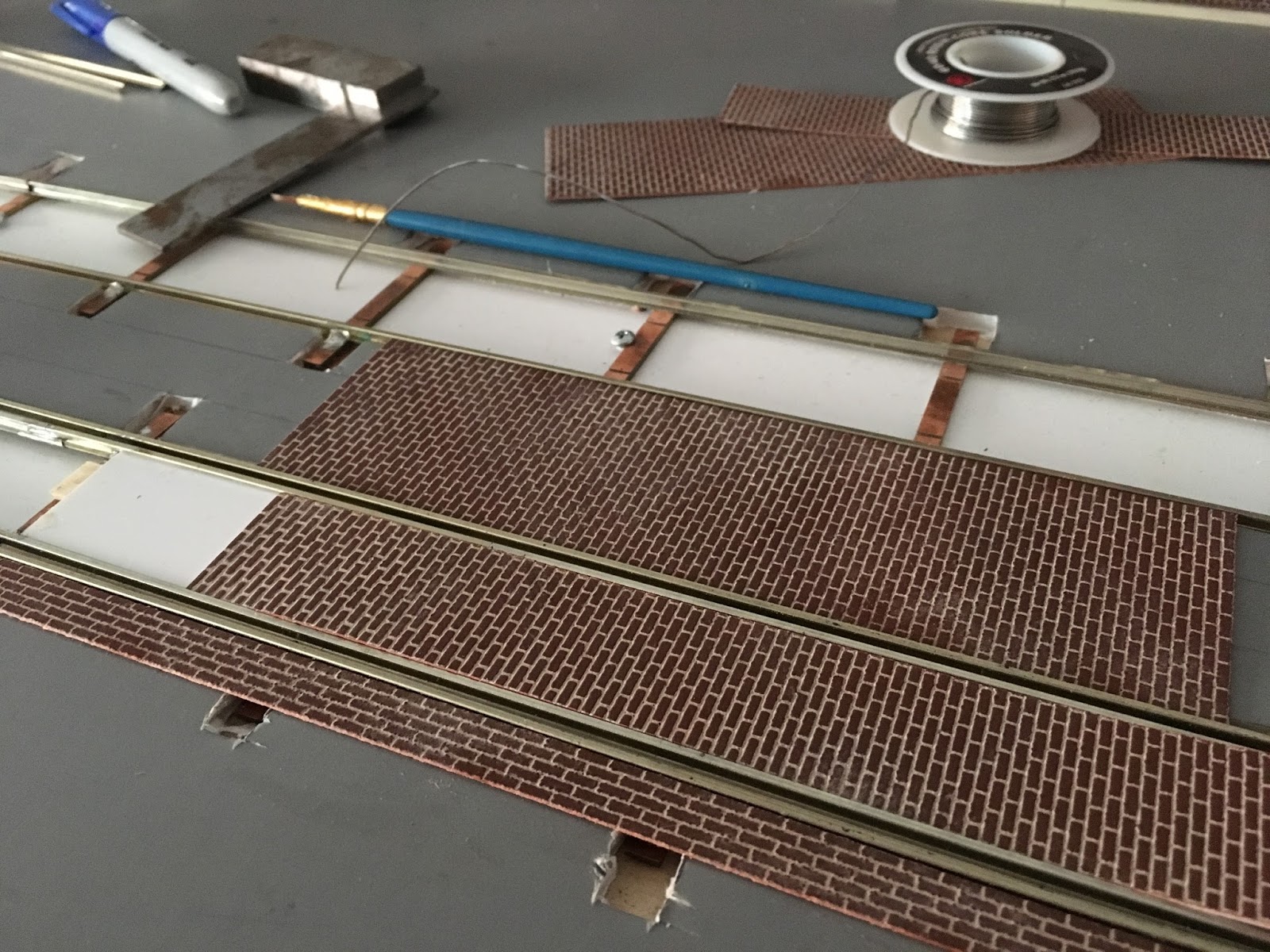
While not perfect for curves (I have yet to solve that problem, I suspect some careful cutting and bending will be used), it is an effective way to pave brick streets with minimal mess. Also, the weight is very light, keeping in mind the portability required for modules.

Additional sections of sheeting are then combined via carefully cutting the brick patterns.

In the below photo, the seams are more visible than they are in person. These sections were not glued down so the seams stand a little proud. In addition, I will be painting and adding additional mortar to assist in camouflaging the seams.


The remaining street surface will be paved with 0.020" styrene sheet to simulate either concrete or asphalt.

Friday, June 2, 2017

Track Work Construction

As mentioned in my prior blog post, I am working on a curved crossing. While work has stalled due to other track being worked on, I did make some additional progress. 


To create the crossing, I use PC board sheets to lay out the actual track crossings. It makes soldering a little easier.

As for the modules, work on the cross overs on each module have been completed.


Each turnout was built separately then combined after some careful trimming. Next time I have to build a cross over I may build it as one unit. However, as this was my first attempt at track laying, I'm happy with the results. The frog size is a  # 3, which is larger than the prototype, but I had the room and wanted to ensure smooth operation.

As these modules need to be portable, in order to "pave" the streets and bury the track work, I've decided to use 3/16" foam core as a base. The track was raised slightly with 0.040" styrene so that the rail head would be slightly raised above the soon to be added street paving.


An advantage of using foam core is its light weight. As these modules are destined to be moved, I wanted to keep the weight as low as possible.I don't "bury" the track in the foam core, but rather cut reliefs for the ties. I can still remove the track if needed for maintenance or adjustments.

Using the foam core as a base, I am paving my streets using brick sheeting.


This small section is being used as a test to make sure that this particular process would indeed work. So far I am satisfied with the results.


If this was "production" and not a test, I would add further mortar (actually drywall joint compound tinted with paint) to the seams between the brick sheets.

On the other module, I've decided to add a "scenic" element of a cross street and some potential future expansion.


These turnouts are somewhat sharper at a # 2.1 which match the 12" curves on the diverging route. The same method of using PC board sheet to solder the actual crossing rails was also used. Also shown is the other cross over that is at the end of this module.

Here are some overall views of both modules:


Saturday, April 8, 2017

End module ideas and roster additions

One significant disadvantage of my current residential situation it that I have quite limited space. However, I would like to explore some options on how I could add a return loop (just for the streetcar trackage, not the elevated) to my modules.

Using the program Templot, I printed out a 2.5 turnout and some 12" radius curves and mocked up a terminal / return loop.


In the above photo, the track has been laid out using paper templates. The section of paper to the right represents the width of my current module and where the track is to be positioned.

This terminal loop would be nicely prototypical as I could model a terminus. However, the "lobe" and required width of the module (imaging the bottom of the photo being the wall ... no space on that side) would be way too wide for my space. It would stick too far out into my limited living space.

As another option, I laid a 12" radius curve over the printouts to see if this would fit better.


As shown in the above photo, I'll still use the same 2.5 turnouts but now the return loop will cross the double track main line. I'll need to add another 2.5 turnout to the other track, But, this configuration is a much more efficient use of the limited space I have. Thus, I've decided to pursue this option.

To begin, I laid some templates out on a piece of plywood:


And I began laying the curved section of track first.


Unfortunately that is as far as I've gotten. Stay tuned for more.

In other news, I've added a few new cars to the roster:


The additions are:

  • Two CA&E 450's, Miller kits, both with Wagner power trucks
  • CNS&M Brill Coach, Clouser body (modified to be a Brill), unpowered
  • CNS&M # 411, scatchbuilt, powered
However, being of limited yard space, I had to get very creative in storage of the new additions. So? On top of the kitchen cabinets for now. Luckily I do not cook much.


Sunday, March 26, 2017

Turnout Construction

As mentioned in my previous post, I'm creating my streetcar turnouts using # 3 templates printed from the program Templot. There are quite a few guides on how to construct turnouts already on the web, but I wanted to document my process.

This was my first ever attempt at hand laying a turnout and it went surprisingly well. It was easy to do and quite a lot of fun. 

I prefer to build my track "on the workbench", so to speak. 

First, some of the tools I use. Shown is the FastTracks jig I am using to create straight sections of track.


Using a piece of wood, I tape down the turnout template I printed out.


I lay out the Right-O-Way point castings next. I use short sections of straight track built using the FastTracks jig to set the gauge for the points.


I next add the various rails. All track is pre-bent using a rail bending tool I also acquired from FastTracks. 


Using a jig I mounted on another board, I pre-make the # 3 frogs. The frog is added next.


Since this turnout will be part of a crossover on closely spaced (3.25") parallel tracks, that it why I have the marks on the divergent side of the turnout. I will eventually trim the turnout down to pair up with the other turnout.

Once the frog is added, I add the remaining guard rails. Since this will be street trackage, all rails receive guard rails.


Since some of my equipment has older Wagner drives, it has a bit larger flanges. Thus, I've decided to make guard rails out of vertical code 125 rail placed next to the running rail. On some test sections of code 125 with code 100 rail soldered on edge I had issues with some equipment running on their flanges.

A left hand turnout was also created in the same manner.


All throughout the process I checked the turnout for gauge using an NMRA gauge, my two three point gauges, a pair of trucks, and once completed, I rolled some equipment through them to check for any issues. On my first turnout I did wind up moving the frog slightly as the trailing truck of my equipment was picking the point of the frog. Un-soldering the frog and correcting the problem was an easy fix.

Friday, March 24, 2017

Track Layout

Since I live in downtown Chicago, space for an O scale layout is certainly at a premium. My layout will consist of two modules, 6 feet long by approximately 20 inches wide.

To keep things interesting and simple, so far the plan will be for a combination of streetcar trackage plus elevated overhead. The streetcar track will consist of two parallel tracks with a cross over at each end of each module.

The style of elevated structure has yet to be determined, but I'm now leaning more towards Lake Street elevated as that would give me the most amount of clearance under the tracks. I would build the eastern style that has the columns at curbside.

The layout of the track:


At hen end of each module, as mentioned above, will be a crossover. I'll leave enough room to park a car at each end also after the turnout. 

I've decided to use # 3 turnouts with a track spacing of 3.25 inches. The templates for the # 3's were drawn with the track layout CAD program Templot. This program is certainly challenging to use, but I was able to persevere and get it to at least print a number 3. I certainly think the CSL equipment I have shouldn't have a problem negotiating this crossover.


The # 3 paper templates will also be used to construct the turnouts using Right-O-Way single point switch castings. Details on how I did that will follow in the next post.

Monday, January 23, 2017

New building flats

I've decided to start 2017 with some new building flats. 

These buildings are based off some prototype builds on south Halstead Ave. in Chicago's Bridgeport neighborhood.


These are just the initial stages of construction. Materials used are N Scale Architect brick sheets and Evergreen styrene strips.