Sunday, November 22, 2015

Building Detailed L structure, Introduction, part 2

In this post I will discuss some of the research methods I use, resources on building elevated structure and some of the tools and materials that will be needed.

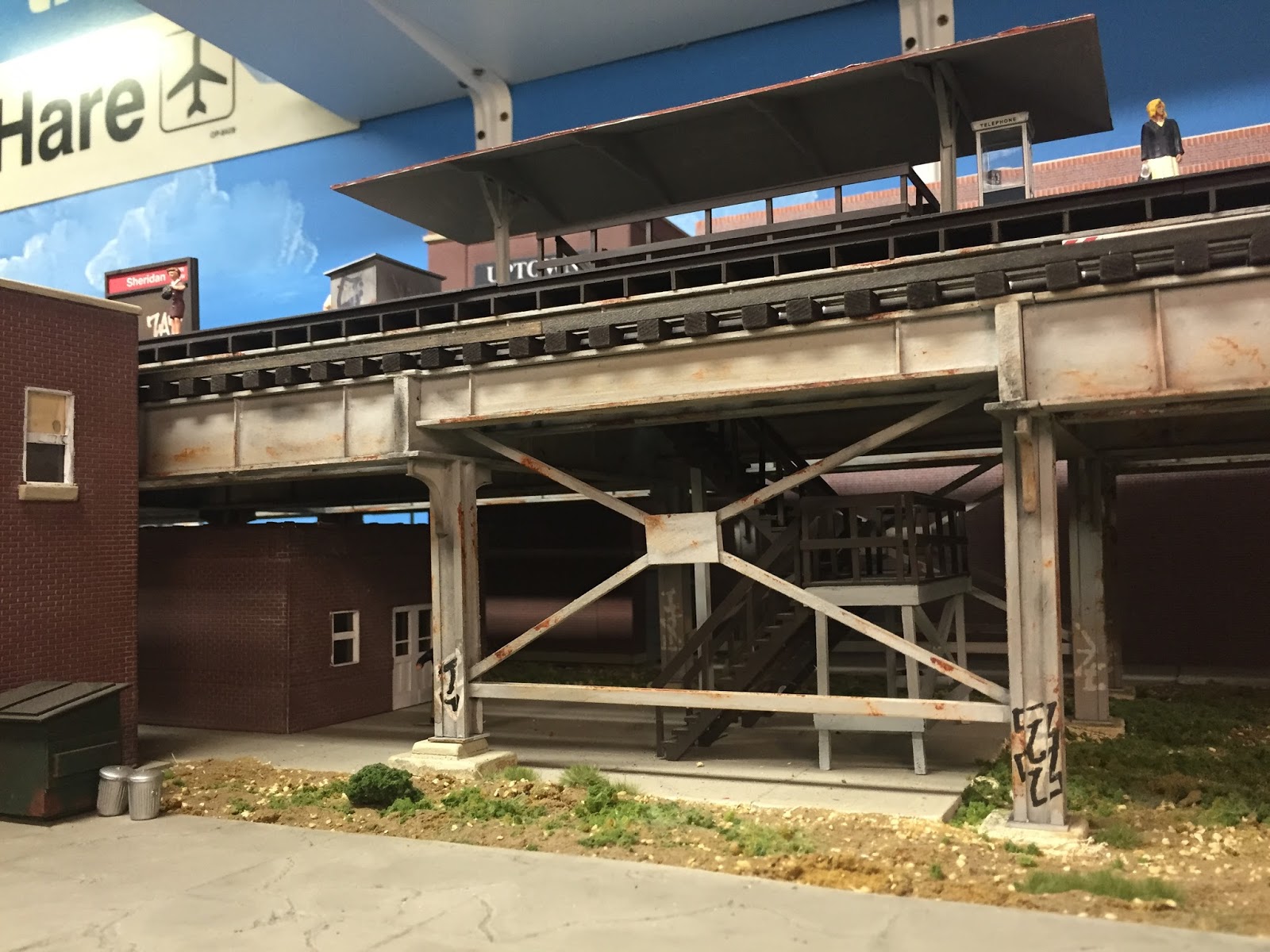
A view down the tracks, with a Jumbotron in the background!
Research

The best research I've found is just to view the structure in person and take lots of photos. Luckily, there are still numerous areas of the system that haven't been updated or modernized so it's pretty easy to find unmolested examples of original structure.

However, in this day and age of heightened security awareness, taking detailed photographs of public transportation infrastructure may cause issues (however innocent or unintentional) with local law enforcement. So, either be very cautious in one's photography or search for other's previously published photographs for reference.

Close up of station support bracket ... taken on the "sly"
Old Lincoln Ave ( NOPE- Clark Street! Thanks for the catch, Don! ). station, taken from the 2011 Illinois Railway Museum Snowflake
Special charter
Damen Avenue station, taken from the 2012 Illinois Railway Museum
Snowflake Special Charter
Lake Street Elevated, taken from the 2013 IRM Back to the 60's
2200 Series Charter
Orignal Met structure canopy support, Damen Ave
From same 2013 IRM Back to the 60's Charter
Wabash Avenue L, junction with Van Buren
From same 2013 IRM Back to the 60's Charter
Wilson Avenue station, from same IRM Back to the 60's charter


Therefore, some other options are:
  • Historical photographs from books and publications: These can be a great resource for viewing original structure. However, most photographers focused mainly on the trains rather than the structure so sometimes details can be lacking.
The "L": The Development of Chicago's Rapid Transit
System, 1888 - 1932 By Bruce Moffat ... a must have
  • Flickr: I've found a lot of close up photographs that people have taken via a search on Flickr. These then can be downloaded for future study. Quite a few folks like to photograph Chicago elevated structure as a study in urban art I gather. I highly recommend the Chicago Transit Authority group on Flickr for some good close up photographs.
  • Google Street View: I've found using Google street view to be one of the best resources available. I can closely view most of the details of the various lines without having to deal with security concerns or less than friendly neighborhoods. 
Original style Met structure from Google Street View
Harrison Street under Rush Medical center
South Side elevated, 318 E 45th street


Resources

Before tackling any project concerning building elevated structure, I highly recommend reading Eric Bronsky's series of articles on building Chicago elevated structure.

These include:

Farewell to the Old El; Mode Railroader, April 1976
Modeling Elevated Rapid Transit Lines, Model Railroader, October 1978
Casting Parts in Polyester Resin, Model Railroader; November 1981
Born to Raise L's; Model Railroader, October 1984


These four articles I believe constitute the "bible" of creating elevated structure and rapid transit modeling and are an absolute must have for any modeler. These articles can be obtained from Model Railroader / Kalmbach Publishing.

A few other useful resources can be found by searching Google Books. Interesting articles include:

Some Features of Construction of the South Side Elevated Railroad; Journal of the Western Society of Engineers; October, 1908
Reconstruction of the South Side Elevated Railroad, Chicago; Electric Railway Review; August 21; 1907

I have barely begun to scratch the surface of the amount of literature available on Google Books and their copies of the Electric Railway Review but it is worth a look.

Tools

The tools needed for this project  are rather simple. To build the masters, I plan on using just basic model railroad tools such as:

  • Xacto knives / hobby knives: I recommend buying blades in packs of 100 from Amazon.com. I do try to change blades frequently. All sheet styrene is cut via the score and snap method. The best styrene scoring tool I've found so far is to use the back of a now dull Xacto blade. That is, instead of using the sharp side, drag the blade backwards. If you make a screeching sound, you are making a good score. For 0.040" sheet, I like to make four or five passes before snapping. If you feel your straight edge move, stop scoring and just proceed to snapping.
  • Metal Rulers: Not so much for measuring, but more for cutting styrene. And, luckily I have several rulers that are 1" (four scale feet in O or the proper height of a solid girder) wide and another that is 1.25" (five scale feet in O or the proper height of a loop style truss girder) wide ... these come in especially handy when cutting girders out of sheet styrene.
  • Glass surface: I use a tempered shelf from an old refrigerator. It makes a flat cutting surface and clean very easily with a single edge razor blade.
  • MEK: For gluing styrene I use straight MEK bought from my local home improvement center. I just keep filling an old Plastruct cement bottle that has a brush built into the lid. I go through a can about once a year, and most of that is used up via spills.
  • Rivet dies: This is the one tool that will be difficult to find. I purchased these a few years ago from a German arts and crafts website based upon a recommendation via a post from the Freerails model railroad forum. Unfortunately  I can no longer locate the site where I purchased these from (they changed URL's) and the instructions are in German, which I do not speak. I used these dies on my resin / scratch built section of structure.
The die set. Styrene is sandwiched between the two piece then an exactly
spaced rivet pattern can then be punched into the styrene.
  • NorthWest Shortlines' The Chopper III: This tool is a must have for reproducing  similar parts in styrene. The length of the Chopper III is a must for O scale. The normal Chopper with the smaller base will be too short.
The Chopper III ... a must have
  • Foam tool holders: I take old pieces of pink scenery foam and cut small squares. I then wrap the foam in duct tape and stick my tools and knives into the foam. These are especially handy for knives and glue bottles. Knives can be stuck into a square to prevent accidental stabbings and the square for the glue bottle acts as an anti-tip base. All it takes is spilling a full bottle of MEK to learn that lesson.
Basic tools: Files, rulers, glue (ACC glue store in a jar) and foam bases


 Materials:


For the longitudinal girders and cross girders, I plan on making all parts from styrene.

Flat cross sections of the girders will be made from 0.040" styrene with a rivet embossed overlay of 0.010" styrene.

Raised rivet strips, flanges and vertical stiffeners will be made from standard dimensional Evergreen strip styrene 0.010" thick. I've managed to create a list strip sizes that work well in creating details and these sizes will be discussed in later the design oriented posts. But, I prefer to use pre-cut styrene strips as much as I can for consistency. No matter how carefully strips are cut, they can never be as accurate as pre-cut Evergreen strips.

More ornate details such as support braces, lattice columns and other complex items will be 3D printed. I've already printed several versions of corner braces and have 3D models created for Metropolitan lattice columns.

3D model of a Ravenswood style support brace
Test 3D model of an ornamental cross girder that would be found
on the Metropolitan elevated structure
3D model of Metropolitan column and cross girder assembly

The next blog post in this series will discuss designing the girders.

Friday, November 20, 2015

Building Detailed L structure, Introduction, part 1

One of the most frequently asked questions I receive is how to build elevated structure. As you can probably guess, this isn't an easy question to answer and of course there are many ways to build elevated structure. I've decided to tackle a long term project of documenting how I envision building well detailed O scale elevated structure. This isn't a particularly complicated modeling endeavor, but it is time consuming and will incorporate several different modeling disciplines including styrene scratch building, 3D printing and resin casting.

Ravenswood style of elevated structure, made from MDF
I envision this process, from start to finish, taking anywhere from six months to a year. This is mostly due to other projects I am working on and budget limitations. Therefore, posts will be somewhat sporadic as time and other modeling allow. But, this is a project I've been wanting to start (building structure is really my favorite aspect of traction modeling) so I figure now is the time to begin.


One takeaway is to understand that no one size or style of construction fits all applications. I will be focusing on the Chicago elevated (for which there are numerous structure styles) but I think the principals are easily translatable for different prototypes.

Goals:

The goals that I envision for this project are:
  • Highly detailed structure. This will include rivet detail, near scale flanges, internal girder bracing and any ornamentation.
  • Easy to produce. Simple components (girders and cross girders) will be scratch built from styrene and more complex shapes will be created via 3D printing. Molds can then be made of these items for rapid reproduction.
  • Easy to assemble / modular in nature. Thought will be given as to how the individual components will go together to ensure that construction will be easy and quick. Thought will also be given to make the structure modular in length. That is, an assembled piece of elevated structure should not be longer than three feet in length. Any longer and undue stress on the model and is very unwieldy. There will be a method of attaching multiple sections.

I'm envisioning a complete system, that once all the component pieces are constructed, rapid assembly of a significant stretch of structure can be built. Since all parts are interrelated on how they will be assembled, I'm going to give significant thought to easy of construction and casting as I progress through the steps.

Prototype:

As mentioned previously, I will be focusing on the elevated structure found in Chicago, and Chicago's elevated system has multiple types of construction. My layout currently consists of two types of Northwestern elevated structure: center column structure (as found on the north/south mainline and outside column structure that is found on the Ravenswood branch). For this project, I've decided to focus on the following three types of structure:
  • Loop Elevated: An obvious choice as this is the type that is most commonly associated with Chicago elevated. This consists of lattice girders and outside support columns. This will be the most difficult to construct due the lattice style of the girders.
  • Lake Street Elevated: Solid girders and columns spaced almost on the curbs. I've decided to focus on this style (found on the eastern portion of Lake Street) rather than center column structure found on the western portion just for easy of construction at this time.
  • Metropolitan Elevated. This is a center column, solid girder and lattice column structure.
The types of structure I wish to model:


Loop Elevated, Wells Street
Lake Street Elevated, photo taken from Google Street View

Underside of Lake Street Elevated, also taken from Google Street View
Metropolitan Elevated, original structure that is still standing mostly unmolested.
Photo taken from Google Street view

My layout currently does not have any streetcar or street based structure so the Loop elevated and Lake Street elevated will give me more options in the future for either expansion or modular additions where I can include street tracks under the structure.


Methods:

My prior methods of building L structure included MDF girders, basswood and various styrene shapes and a combination of cast girders and individually built columns.
Some thoughts on these prior methods:

MDF Style -

The MDF style of construction is currently used on approximately 75% of my layout.

Advantages:
  • Easy to built. Not very complicated in construction. View my prior blog posts for construction photos.
  • Quick to build. Assembly moves rather rapidly once the component parts are assembled
  • Low cost. MDF is inexpensive, additional components such as basswood and styrene as also inexpensive.

Disadvantages:
  • MDF. Cutting MDF is pure misery due to the very, very fine dust created. Dust will go everywhere so cutting inside, especially in the layout room, is not recommended.
  • Details. The structure lacks finer details such as rivets and lattice columns or girders can't be created
  • Tools required. In order to cut the MDF into the 1" wide strips a table saw is required. In addition, a miter saw was needed to cut the girders to length. I had these tools prior to the start of layout construction fortunately.
MDF Elevated structure in the style of the Northwestern Elevated main line.

MDF girders with basswood flanges. Columns are basswood with
styrene applied for details. Braces are styrene.

Cast Resin / Scratch built columns and cross girders with some 3D printed components

My newest stretch of structure consists of this type. The girders are cast resin, styrene strips are then added to the girder castings to make the flanges. All columns and cross girders are scratch built individually.

Advantages:
  • More detail: All the girders and columns have rivet detail. The girder flanges are more to scale, and the column support braces are fully detailed.
  • Easy to assemble. Gluing styrene to styrene is easier when appropriate plastic cement (I use straight MEK) can be used.
  • Speed of creation of girders / column support braces via resin castings. Molds were made for double sided girders (flanges were not included) and the column support braces. Once made, multiple copies could be made quickly.

Disadvantages
  • Lack of assembly forethought. When I made the masters for the girders, I did not add the top and bottom flanges. Therefore, for each girder (which consisted on an outside casting and an inside casting) I had to cut a strip of styrene for both the top and the bottom of the girder to act as the flange. I made these too wide and could not buy a commercially available piece of strip styrene and therefore had to cut each strip from sheet styrene. In addition, on the inner girder masters I didn't account for cross bracing. It was more difficult to add cross bracing to the structure as some of the details on the girders were in the way.
  • Scratch built cross girders. Since the section of structure I was building had cross girders with different lengths due to future station, this wasn't a big issue but it did slow construction and required additional amounts of styrene components.
  • Scratch built columns. Each column was scratch built with individual rivet details added to each column. This took a substantial amount of time and material. I'm still not 100% finished with these columns as I still need to add the footing support braces to some of the columns. Each one is built individually.
Northwestern Elevated n Ravenwood style
Girder masters (top and bottom flanges added AFTER molds made).
From top to bottom: Met top two, Northwestern next four and
an old Loop elevated resin casting I acquired awhile ago.

Cross girder detail and 3D printed corner bracing.

New structure (I'll call this version 3.0):

Using the knowledge I've gained in building the previously discussed two styles of elevated structure, my expectations for version 3.0 will be:

  • Girders: Girders will be scratch built from styrene, with appropriate rivet detail and bracing. I will model these as close to the prototype (depending on the style of structure) as possible. Girder flanges will be included in the masters and mounting methodology to the cross girders will be thought out before the masters are made. These girders will be fully detailed on both sides (two masters made - outer girder face and inner girder face). However, the inner girder casting will have accommodations made for cross bracing for the two girders that support the track. The girders will consist of two halves to make casting easier.
  • Cross girders: These too will be scratch built from styrene and molds made for casting multiple copies. Additional thought will be given to attaching the longitudinal girders for optimal strength. I may have some cross girders 3D printed to maximize rivet detail or lattice detail.
  • Columns: Depending on the style, the columns will either be scratch built from styrene (for a solid column) or 3D printed for lattice columns. Solid columns will be the hardest portion of this project as they will most likely require a two part mold. The lattice girders can be cast flat as a column would be made of multiple components.

I envision the project flow / steps to be:
  1. Create outside girder masters
  2. Create inside girder masters, keeping in mind any cross bracing that will need to be added.
  3. Create any support brackets via 3D printing.
  4. Create the cross girders
  5. Create the columns either via scratch building or 3D printing
  6. Make molds of all the components

This ends part one to the introduction. In the next post in this series I will discuss research methodology, resources and tools needed. I will try to document the building process as much as I can along the way to share this information.


Sunday, November 15, 2015

Updates for mid-November 2015

I've decided to start adding some additional building to my Sheridan Road curve section of the layout ...

Still in process of painting the buildings

So far in this curved section, I've added a background apartment building flat, a warehouse type brick/concrete flat, a re-purposed apartment building and my grocery store.

A North Shore combine rolls past the still in construction apartment building.

A view of the whole corner.
A short while later additional painting of the buildings was completed:

Window details still need to be added and a full interior will be added to the grocery store building on the lower left
A little better with additional paint.
I've also improved the fluorescent lighting along my newest L extension module:

Light now shines more on the front of the structure.

It makes photography much easier and details on the structure seem to "pop" more.
Much better lighting!

After improving the lighting, I knew I had to tackle the white concrete wall behind the module. As this section of layout is removable due to utilities and a window, I decided to attached the backdrop to the bench work and make it removable.


I screwed 1 x 2 wood supports to the bench work (that just rests on cleats attached to the adjacent bench work) then using Velcro (for easy removal) just attached MDF panels to the vertical supports. The removable nature of the backdrop does leave a seam, but I'll camouflage that with a structure at some point. 

A view down the layout with the new corner buildings:


Shown in the above photo is a large white (actually styrene) building behind the Sheridan Road station. This is the core of a new brick and concrete structure that will act as a backdrop for the trains at the Sheridan Road station.


The core of the building is made of 1/4" plywood to which I attached the styrene. Larger styrene structures (this one 12" x 16") need lots of interior bracing. The plywood will prevent any warping. Also shown in this picture are my still uncompleted Island Model Works 2200 series cars. One of these days I will finish those!

And, fresh out of the paint shop is my Northwestern Motor:


Using Tru-Color paints, I was able to successfully match the colors of the trailer which was painted over 20 years ago (and not by me).

Paints used were:


  • Rich Oxide Brown
  • SP Daylight Orange
  • Erie Lackawanna Gray