One of the most frequently asked questions I receive is how
to build elevated structure. As you can probably guess, this isn't an easy
question to answer and of course there are many ways to build
elevated structure. I've decided to tackle a long term project of documenting
how I envision building well detailed O scale elevated structure. This isn't a
particularly complicated modeling endeavor, but it is time consuming and will
incorporate several different modeling disciplines including styrene scratch
building, 3D printing and resin casting.
 |
| Ravenswood style of elevated structure, made from MDF |
I envision this process, from start to finish, taking
anywhere from six months to a year. This is mostly due to other projects I am
working on and budget limitations. Therefore, posts will be somewhat sporadic
as time and other modeling allow. But, this is a
project I've been wanting to start (building structure is really my favorite
aspect of traction modeling) so I figure now is the time to begin.
One takeaway is to understand that no one size or style of
construction fits all applications. I will be focusing on the Chicago elevated
(for which there are numerous structure styles) but I think the principals are
easily translatable for different prototypes.
Goals:
The goals that I envision for this project are:
- Highly detailed structure. This will include rivet detail, near scale flanges, internal girder bracing and any ornamentation.
- Easy to produce. Simple components (girders and cross girders) will be scratch built from styrene and more complex shapes will be created via 3D printing. Molds can then be made of these items for rapid reproduction.
- Easy to assemble / modular in nature. Thought will be given as to how the individual components will go together to ensure that construction will be easy and quick. Thought will also be given to make the structure modular in length. That is, an assembled piece of elevated structure should not be longer than three feet in length. Any longer and undue stress on the model and is very unwieldy. There will be a method of attaching multiple sections.
I'm envisioning a complete system, that once all the
component pieces are constructed, rapid assembly of a significant stretch of
structure can be built. Since all parts are interrelated on how they will be
assembled, I'm going to give significant thought to easy of construction and
casting as I progress through the steps.
Prototype:
As mentioned previously, I will be focusing on the elevated
structure found in Chicago, and Chicago's elevated system has multiple types of
construction. My layout currently consists of two types of Northwestern
elevated structure: center column structure (as found on the north/south
mainline and outside column structure that is found on the Ravenswood branch).
For this project, I've decided to focus on the following three types of
structure:
- Loop Elevated: An obvious choice as this is the type that is most commonly associated with Chicago elevated. This consists of lattice girders and outside support columns. This will be the most difficult to construct due the lattice style of the girders.
- Lake Street Elevated: Solid girders and columns spaced almost on the curbs. I've decided to focus on this style (found on the eastern portion of Lake Street) rather than center column structure found on the western portion just for easy of construction at this time.
- Metropolitan Elevated. This is a center column, solid girder and lattice column structure.
The types of structure I wish to model:
 |
| Loop Elevated, Wells Street |
 |
| Lake Street Elevated, photo taken from Google Street View |
 |
| Underside of Lake Street Elevated, also taken from Google Street View |
 |
| Metropolitan Elevated, original structure that is still standing mostly unmolested. Photo taken from Google Street view |
My layout currently does not have any streetcar or street
based structure so the Loop elevated and Lake Street elevated will give me more
options in the future for either expansion or modular additions where I can
include street tracks under the structure.
Methods:
My prior methods of building L structure included MDF
girders, basswood and various styrene shapes and a combination of cast girders
and individually built columns.
Some thoughts on these prior methods:
MDF Style -
The MDF style of construction is currently used on approximately 75% of
my layout.
Advantages:
- Easy to built. Not very complicated in construction. View my prior blog posts for construction photos.
- Quick to build. Assembly moves rather rapidly once the component parts are assembled
- Low cost. MDF is inexpensive, additional components such as basswood and styrene as also inexpensive.
Disadvantages:
- MDF. Cutting MDF is pure misery due to the very, very fine dust created. Dust will go everywhere so cutting inside, especially in the layout room, is not recommended.
- Details. The structure lacks finer details such as rivets and lattice columns or girders can't be created
- Tools required. In order to cut the MDF into the 1" wide strips a table saw is required. In addition, a miter saw was needed to cut the girders to length. I had these tools prior to the start of layout construction fortunately.
 |
| MDF Elevated structure in the style of the Northwestern Elevated main line. |
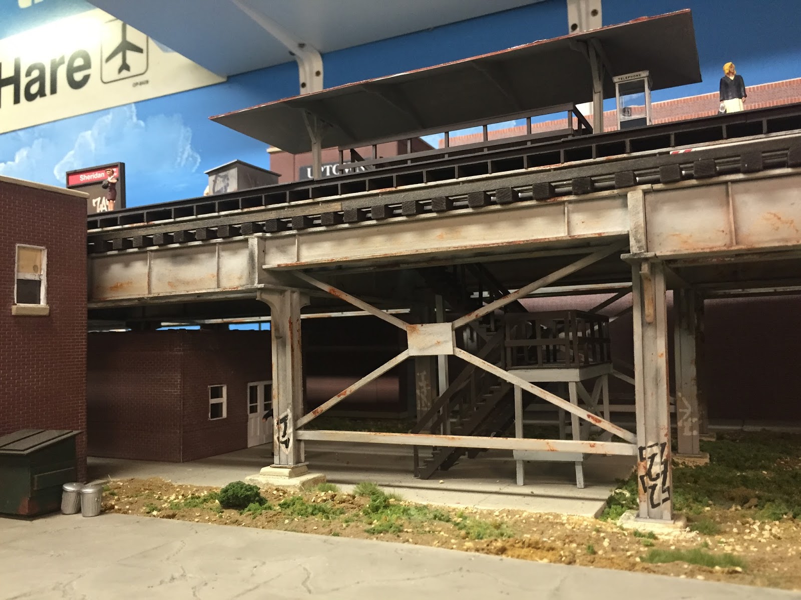 |
| MDF girders with basswood flanges. Columns are basswood with styrene applied for details. Braces are styrene. |
Cast Resin / Scratch built columns and cross girders with
some 3D printed components
My newest stretch of structure consists of this type. The
girders are cast resin, styrene strips are then added to the girder castings to
make the flanges. All columns and cross girders are scratch built individually.
Advantages:
- More detail: All the girders and columns have rivet detail. The girder flanges are more to scale, and the column support braces are fully detailed.
- Easy to assemble. Gluing styrene to styrene is easier when appropriate plastic cement (I use straight MEK) can be used.
- Speed of creation of girders / column support braces via resin castings. Molds were made for double sided girders (flanges were not included) and the column support braces. Once made, multiple copies could be made quickly.
Disadvantages
- Lack of assembly forethought. When I made the masters for the girders, I did not add the top and bottom flanges. Therefore, for each girder (which consisted on an outside casting and an inside casting) I had to cut a strip of styrene for both the top and the bottom of the girder to act as the flange. I made these too wide and could not buy a commercially available piece of strip styrene and therefore had to cut each strip from sheet styrene. In addition, on the inner girder masters I didn't account for cross bracing. It was more difficult to add cross bracing to the structure as some of the details on the girders were in the way.
- Scratch built cross girders. Since the section of structure I was building had cross girders with different lengths due to future station, this wasn't a big issue but it did slow construction and required additional amounts of styrene components.
- Scratch built columns. Each column was scratch built with individual rivet details added to each column. This took a substantial amount of time and material. I'm still not 100% finished with these columns as I still need to add the footing support braces to some of the columns. Each one is built individually.
 |
| Northwestern Elevated n Ravenwood style |
 |
| Girder masters (top and bottom flanges added AFTER molds made). From top to bottom: Met top two, Northwestern next four and an old Loop elevated resin casting I acquired awhile ago. |
 |
| Cross girder detail and 3D printed corner bracing. |
New structure (I'll call this version 3.0):
Using the knowledge I've gained in building the previously
discussed two styles of elevated structure, my expectations for version 3.0
will be:
- Girders: Girders will be scratch built from styrene, with appropriate rivet detail and bracing. I will model these as close to the prototype (depending on the style of structure) as possible. Girder flanges will be included in the masters and mounting methodology to the cross girders will be thought out before the masters are made. These girders will be fully detailed on both sides (two masters made - outer girder face and inner girder face). However, the inner girder casting will have accommodations made for cross bracing for the two girders that support the track. The girders will consist of two halves to make casting easier.
- Cross girders: These too will be scratch built from styrene and molds made for casting multiple copies. Additional thought will be given to attaching the longitudinal girders for optimal strength. I may have some cross girders 3D printed to maximize rivet detail or lattice detail.
- Columns: Depending on the style, the columns will either be scratch built from styrene (for a solid column) or 3D printed for lattice columns. Solid columns will be the hardest portion of this project as they will most likely require a two part mold. The lattice girders can be cast flat as a column would be made of multiple components.
I envision the project flow / steps to be:
- Create outside girder masters
- Create inside girder masters, keeping in mind any cross bracing that will need to be added.
- Create any support brackets via 3D printing.
- Create the cross girders
- Create the columns either via scratch building or 3D printing
- Make molds of all the components
This ends part one to the introduction. In the next post in
this series I will discuss research methodology, resources and tools needed. I will try to document the building process as much as I can along the way to share this information.
Rubber molded articles - R and G polymers is one of the leading company for the production of molded articles and more particularly to an improved method for molding such articles as are made of rubber containing quality materials.
ReplyDelete