Friday, December 20, 2013

Merry Christmas to all!


The CTA's annual holiday train made its appearance on the layout over the weekend. Santa made an appearance and got quite a few Christmas lists from the local kids.


Merry Christmas all! Hopefully Santa's train isn't delayed too much this year.

Tuesday, December 17, 2013

3D Printing Update

I have two 3D printing projects that I am currently working on: a model of a CRT 4000 series car and Metropolitan L style structure.


Philosophy:

The goal is to make a 3D print that can be used as a master to make molds for casting. I chose CTA car # 4256 since it is a modernized 4000 series with the oval windows which I haven't seen in model form before. I thought that the oval windows would be the most challenging to reproduce.

With the 3D model stored in a file on the PC, it is hoped that changes to window styles and doors (for baldies and plushies, modernized, original rectangular windows, work cars, etc.) could be made in the 3D program rather easily then printed as desired. 

The CRT/CTA 4000 series car isn't currently offered in O scale, although Q-Car Company resin shells appear infrequently on E-Bay. With this, the complexities of the end of the cars and precision needed for the oval windows makes 3D printing an option for modeling this car as some of the details are beyond my modeling ability.

I worked off the following plan for the 4000 series car, and not from an existing model. I don't want any hints or suggestions of piracy.


Tools used:

Google Sketch-up 8 - for the 3D modeling (free). Sketch-up .skp files saved as .dae files
Mesh Labs to convert the .dae files to .stl files
Shapeways for printing

Design Considerations:

Within the limits of Shapeway's materials, I tried to stay as close to scale accuracy as possible, On the models below, all details and dimensions were taken from the above plan. Where I didn't have measurements, I extrapolated from known measurements. 

Outcome:

Given the size constraints of the Shapeways' materials, the ends of the cars were printed in Frosted Ultra Detail (FUD) and the side was printed in Frosted Detail. The FUD has a greater resolution.

(Note: there is some extra "roughness" to the photos. I've primed the parts with auto-primer and in some cases, coverage wasn't 100% which makes for a splotchy appearance, sanding hasn't been 100% completed and in some areas I forgot to remove all the sanding dust).

Below is a 3/4 view of the front and side:


A view of the side:


And of the ends:


Issues and problems:

The ends, being printed in FUD, turned out acceptable. The rivet detail is very crisp, and the smallest details are legible. There is some "striping" (print lines from the 3D printer), but after one coat of primer, most of these lines can be sanded out.

Car Ends:

End # 1:


Note some roughness in the door panel and by the trolley wire spool. I haven't sanded those areas yet. But, the anti-climber detail turned out well, along with a floor mat that sits in front of the door. Again, the rivets are 3/4" in diameter and 3/4" high. I could probably reduce the height of the rivets to 1/2" in height. They are a bit large.

End # 2:


Again, I haven't sanded the door, and still need to sand around the bottom row of rivets.

However, with the ends, as there are some undercuts with the anti-climber, making a one piece mold probably wouldn't work. So, for production cars, the ends would probably need to be made from actual 3D print-outs.
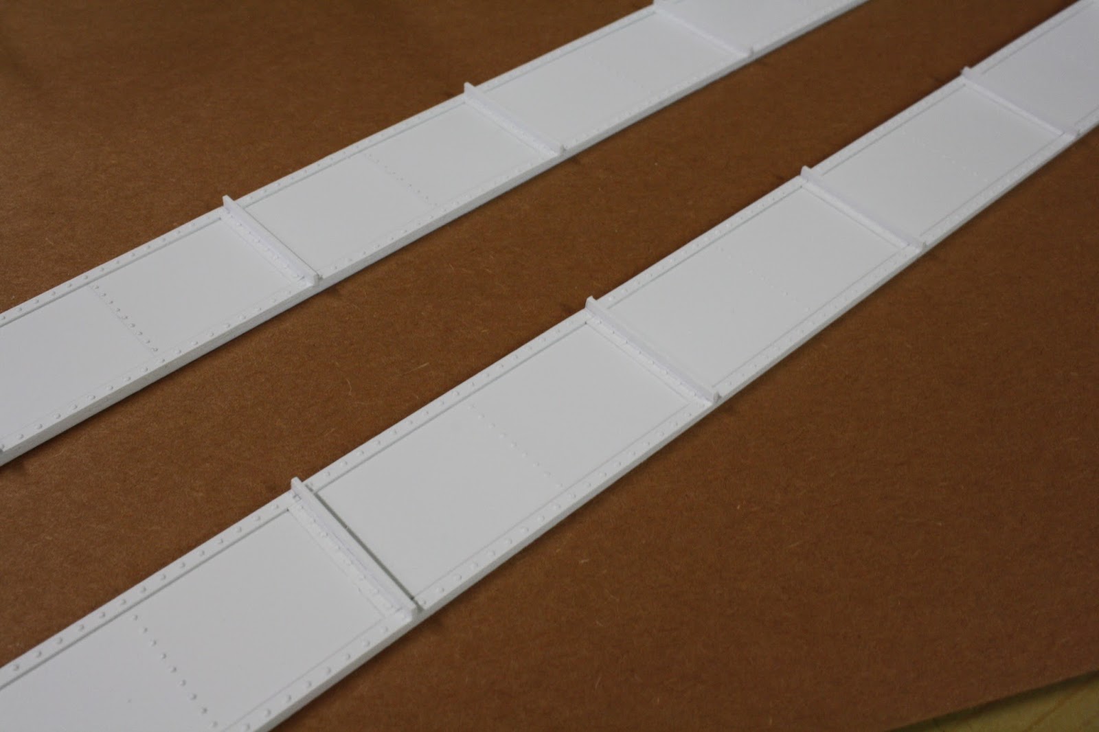
Side:

The side was printed using Frosted Detail, as the size was too big for FUD. Also, I rushed this model to Shapeways to take advantage of a Black Friday discount, thereby resulting in a couple of errors on my 3D modeling.


The car side still needs some work, some of which was caused by the errors I had with rushing my 3D model to Shapeways.

The rivet detail was done at 3/4" in diameter by 1/2" high, with the 1/2" in rivet height being very close to the limits of the Frosted Detail's resolution. 

Also, with the larger flat surfaces of the side, the "striping" effect of the 3D printing process is much more pronounced. Note the following pictures:

The side is the same height as the ends. However, since propped up on a piece of construction paper, the side sits a little higher. Again, the roughness in the front is mostly caused by very splotch application of primer:


Note the area below in the red box. Some of the "striping" effect can be seen. The rest of the door has been sanded with two coats of primer. I didn't have an sanding sticks, so close-in sanding by the sides of the door wasn't possible. With better sanding, I think a smoother finish can be achieved.


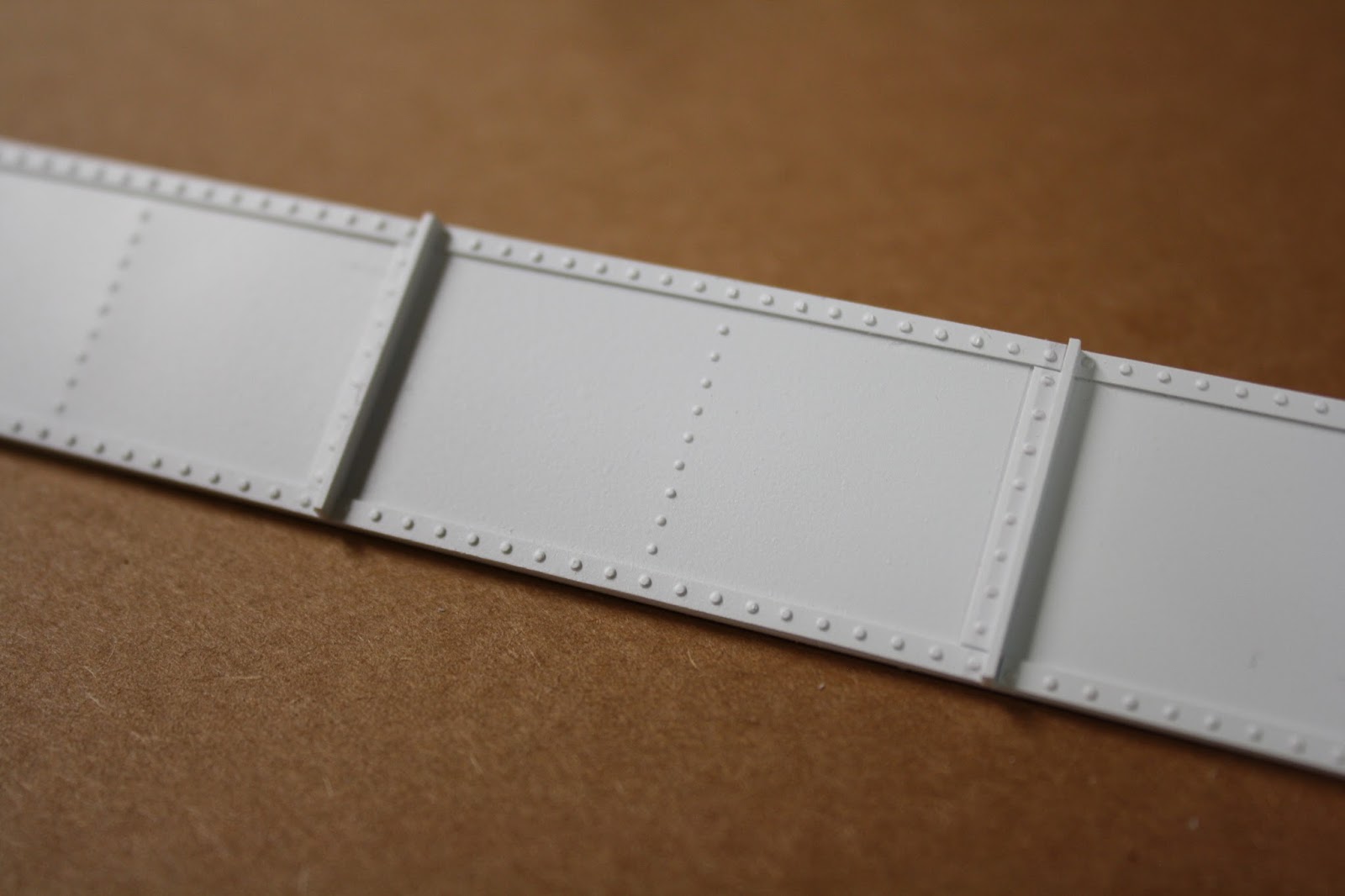
In the following picture, the rivet detail was basically sanded away. Again, I made the mistake of making the rivets only 1/2" high, which really didn't print too clearly. However, in areas such as the horizontal belt rail, the rivet detail was much more clear and legible. The rivets in the letter board are less legible, but still acceptable. The level of "striping" in the letter board, while visible in the below photo, isn't that noticeable in the real model.


The following photo shows that the vertical line of rivets really seemed to exaggerate the "striping" effect on the flat areas. It also shows some of the 3D model errors that I had. The vertical rivets have been mostly sanded away, but "striping" was most evident right next to the rivet line.


Another view of where rivet detail has caused "striping". In this area next to the door, I tried to add some rivets as they appear on the prototype. However, the flat surface definitely seems to exaggerate the lines. Note that the rivet detail on the horizontal belt rail and on the rivet detail underneath the door turn out acceptably well.


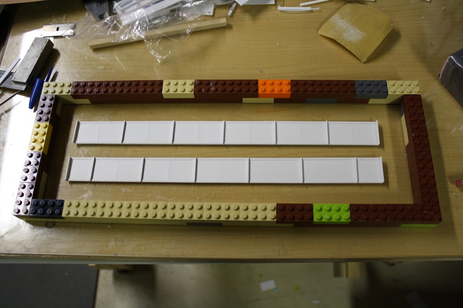
And some other views of the side:


Overall, I think that the side is about 50% acceptable. The window detail turned out very well, and the gaskets around the oval windows are visible as they are 1/2" wide by 1/2" in height. Also, the precision of making consistent oval windows is a benefit.

However, I do need to work out the rivet detail on the bottom half of the car. I have two options:

  • Leave of the rivet detail in the flat surfaces to limit the "striping" effect and add rivet decals in "post production". I'm just not sure how rivet decals will appear in the molds.
  • Increase the diameter and height of the rivets to make them more pronounced and more aggressively sand around these areas with proper sanding tools (like sanding sticks) to get a smoother finish.
Right now, I am undecided on which course of action to take. The goal of the 3D printing was to have the rivet detail included, but I'm not sure how well decals will be able to precisely replicate the original. With the 3D model, I can directly replicate the patterns as they appear on the plans.

I am working on side plan 3.0, so stay tuned.

Met L structure:

In addition to the 4000 series car, I've also been working on creating a set of masters to replicate the Met L structure. The goal is to make a set of columns, cross beams and other details that can be used as a "system" to quickly mold, cast and create L structure in the Met style.

So far I've printed two sample columns, testing various lattice styles.

The column on the left is more prototypical accurate, but I like the thinner lattice style on the column on the left. I've since made a third 3D model that combines the best features of both column. These columns are basically "flat", so making a mold won't be an issue. Two sides will make a column along with a center "spacer" section, which I also have a 3D model for (not yet printed)/

Both columns were printed in FUD:


Some close up views:


Note in the last picture the base has bolt detail that is vertically oriented. This has since been removed from the 3D model as making a mold of this would be difficult. A 3D model of the base has been made and would be printed and cast separately.

The L structure will be a complete system of 3D parts that can be printed and cast for easy replication. The amount of clean up and sanding on these smaller parts is significantly less than the 4000 car side. 


Saturday, November 16, 2013

New business open!

Business is booming and the economy is finally picking up! Well, maybe not in truth, but just finished Elevated Records.


Sunday, October 27, 2013

Update for October, Structures part 2

This weekend I finished painting the new background apartment building:


Its nice to have a building behind the platform, that way the platform seems to be a little more visible.

Sunday, October 20, 2013

Updates for October - Structures

For the last few weeks I've taken a break from casting L structure (out of resin) and decided to build a couple of buildings. For some reason, I usually work on several at a time.

At my Southport station, I've decided to work on three buildings on the left side of the street:


First will be a "sliced: building. I wanted something next to the station, but a full building wouldn't fit. So, I built the building as if it were sliced by the edge of the layout.


A full size building wouldn't fit, so I decided to make a one story building. It most likely will be a news stand. The fence on top is to hopefully keep folks from the soon to be installed station stairs from making their way onto the roof.


To the right of this building will be the station head house. So far I've just started on the front facade. I'll also need to add additional sidewalks to the side and a roto-gate for easy exit from the station.

And along the backdrop I'm building a three story apartment building as shown below:


I want to use these buildings as a backdrop to the station platform as shown in the below picture:


The building on the left in the above picture was a "test" subject for some mortar techniques I was trying out. I'll probably keep in there after I add some additional height to the base (right now its propped up as its actually only two stories tall).

In addition to these buildings, I've started another apartment building for the Sheridan Road curve:


Obviously none are close to being done, and I still need to add additional details to other buildings, but I do enjoy creating these buildings.

I have also begun work on re-doing my 3D drawing of the CTA 4000 series car. I hope to have a new print done in a couple of weeks.

Sunday, September 8, 2013

Slow progress on the new structure.

I have begun laying out the girders for the new section along the fuse panel wall.


This picture shows how I lay out the girders. I make a layout on top of the track with the girders, and glue the long girders to the cross girders upside down. The above shows how I am laying out the structure. This structure is my newer version taking from resin castings.

A close up:


So far I've only made casting of the long girders. For the cross girders and columns, I will scratch build from styrene shapes. My columns are pretty thin in cross section, so I'm not sure how a casting would work.

The girders are made up of a sandwich of a center piece of 0.040" styrene and two castings. The flanges, of which only the bottom flange is on now, is made from 0.030" styrene. The overall width is about 3/8" of an inch on the flanges. A little wider than prototype, but since it is structural I didn't want to go too thin. 

This section is built on a piece of benchwork that hangs from benchwork on either side so I can be removed in a hurry. So, I am not going to attach this structure to the other structure. It will be stand-alone.

Also, congratulations to the Bears on the home opener win. A TV in the layout room, while not the most accurate scenic backdrop, is a must have (sorry for not having the Bears actually on, this was taken after the win)!


And another photo I had just taken:


The building on the right is an Ameritown kit and the one on the left is one of my first scratch building efforts. I'm getting the itch to redo this block and combine these two .... but I've got a lot of projects so that might take a while. I guess a good goal is to always strive to improve and learn.

Also, I was fortunate enough to finally be able to call into Model Rail Radio, a model railroad post cast conducted in a radio show style format hosted by Tom Barbalet. Its a great show and I would highly recommend listening and Skyping in if you can. The address is: http://www.modelrailradio.com/ . Tom does a fantastic job in promoting the hobby and creating a virtual hobby show where folks can just drop in and chat.

Sunday, August 18, 2013

A riveting time, molding, and expansion

My current L structure was built for ease and speed of construction. I wanted to get a fair amount on the layout up and functional so I could enjoy it more quickly.

However, I've always wanted to make a more detailed structure. One issue that prevented me from doing this was determining what the best way to add rivets would be. Since I also planned on casting the sections to speed construction, I didn't think using rivet decals (such as those provided by either Archer or Micromark) would work out too well. I wasn't sure as to how they would look after being cast.

So, a while back, I ordered a set of riveting dies from Germany. Unfortunately I can't locate the name of the website that I ordered it from.

I have made a straight 12" (48 feet) section, and have modeled both sides of the girder:


A closer view of the rivet details:


Using these two sides (front and back), I will make castings of both, and sandwich a piece of 0.080" styrene between the halves to make a girder. I will then add styrene strips to the bottom and top of the girder to make the flanges. The castings will be more decorative while the 0.080" core will make up most of the strength.

The dies, which I believe are actually for 1:43.5 or European O scale:


For the strips of rivets, the proper die is selected and placed in the metal carrier. I have made a small stryene holder to hold everything in place:


Putting in the bottom die and aligning the styrene strip (in this case 0.015" x 0.080"):


Then put the top die in place and start pressing away. The bottom die prevents the styrene from deforming, so the rivets turn out very nice.


The rivets on the web of the girder are done in a similar manner. The proper die is selected (again I made a small styrene alignment tool):


Line everything up and start punching away. Again I am using 0.015" styrene.


Then, after priming the girders white, I made a mold box out of borrowed Legos. I seal the Legos to my plate of glass using Vaseline, and "glue" the girders to the glass also with Vaseline. The Vaseline won't prevent the silicone mold material from completely creeping under the masters, but it'll keep them from "floating" up.


For making a mold, I use the following materials I get from Reynolds Advanced Materials. They have a store in Countryside, IL, that is conveniently on my way home from work.


I don't use a pressure vessel, so, its best efforts. The mold filled with silicone rubber:


The material sets up in about four hours, but I like to leave it sit overnight to be sure. I'll post a follow-up to see how this works. I ran low on silicone so I had to use some old stuff I had laying around...not sure how that will work.

Benchwork expansion:

I built an approximately 9' long by 30" wide shelf expansion that will eventually be a terminal of some kind on the other side of my layout / utility basement room:


I had to relocate most of my signs, but that's a small price to pay for more layout. I am also making a connection behind the hot water heater to the rest of the layout. The far left section of the benchwork is removable so I can, if ever needed, remove the hot water heater.

The signs were moved to the other side of the layout. I've also re-purposed some of my old kitchen cabinets for additional storage. In the picture above, the cabinets are underneath the new benchwork. In the below, I put a large wall cabinet on wheels so I can move it out of the way.


I've also begun mocking up the staircase to the Southport Station:


And a view down the other side of the layout, with some base cabinets, but still very messy.