Saturday, November 16, 2013

New business open!

Business is booming and the economy is finally picking up! Well, maybe not in truth, but just finished Elevated Records.


Sunday, October 27, 2013

Update for October, Structures part 2

This weekend I finished painting the new background apartment building:


Its nice to have a building behind the platform, that way the platform seems to be a little more visible.

Sunday, October 20, 2013

Updates for October - Structures

For the last few weeks I've taken a break from casting L structure (out of resin) and decided to build a couple of buildings. For some reason, I usually work on several at a time.

At my Southport station, I've decided to work on three buildings on the left side of the street:


First will be a "sliced: building. I wanted something next to the station, but a full building wouldn't fit. So, I built the building as if it were sliced by the edge of the layout.


A full size building wouldn't fit, so I decided to make a one story building. It most likely will be a news stand. The fence on top is to hopefully keep folks from the soon to be installed station stairs from making their way onto the roof.


To the right of this building will be the station head house. So far I've just started on the front facade. I'll also need to add additional sidewalks to the side and a roto-gate for easy exit from the station.

And along the backdrop I'm building a three story apartment building as shown below:


I want to use these buildings as a backdrop to the station platform as shown in the below picture:


The building on the left in the above picture was a "test" subject for some mortar techniques I was trying out. I'll probably keep in there after I add some additional height to the base (right now its propped up as its actually only two stories tall).

In addition to these buildings, I've started another apartment building for the Sheridan Road curve:


Obviously none are close to being done, and I still need to add additional details to other buildings, but I do enjoy creating these buildings.

I have also begun work on re-doing my 3D drawing of the CTA 4000 series car. I hope to have a new print done in a couple of weeks.

Sunday, September 8, 2013

Slow progress on the new structure.

I have begun laying out the girders for the new section along the fuse panel wall.


This picture shows how I lay out the girders. I make a layout on top of the track with the girders, and glue the long girders to the cross girders upside down. The above shows how I am laying out the structure. This structure is my newer version taking from resin castings.

A close up:


So far I've only made casting of the long girders. For the cross girders and columns, I will scratch build from styrene shapes. My columns are pretty thin in cross section, so I'm not sure how a casting would work.

The girders are made up of a sandwich of a center piece of 0.040" styrene and two castings. The flanges, of which only the bottom flange is on now, is made from 0.030" styrene. The overall width is about 3/8" of an inch on the flanges. A little wider than prototype, but since it is structural I didn't want to go too thin. 

This section is built on a piece of benchwork that hangs from benchwork on either side so I can be removed in a hurry. So, I am not going to attach this structure to the other structure. It will be stand-alone.

Also, congratulations to the Bears on the home opener win. A TV in the layout room, while not the most accurate scenic backdrop, is a must have (sorry for not having the Bears actually on, this was taken after the win)!


And another photo I had just taken:


The building on the right is an Ameritown kit and the one on the left is one of my first scratch building efforts. I'm getting the itch to redo this block and combine these two .... but I've got a lot of projects so that might take a while. I guess a good goal is to always strive to improve and learn.

Also, I was fortunate enough to finally be able to call into Model Rail Radio, a model railroad post cast conducted in a radio show style format hosted by Tom Barbalet. Its a great show and I would highly recommend listening and Skyping in if you can. The address is: http://www.modelrailradio.com/ . Tom does a fantastic job in promoting the hobby and creating a virtual hobby show where folks can just drop in and chat.

Sunday, August 18, 2013

A riveting time, molding, and expansion

My current L structure was built for ease and speed of construction. I wanted to get a fair amount on the layout up and functional so I could enjoy it more quickly.

However, I've always wanted to make a more detailed structure. One issue that prevented me from doing this was determining what the best way to add rivets would be. Since I also planned on casting the sections to speed construction, I didn't think using rivet decals (such as those provided by either Archer or Micromark) would work out too well. I wasn't sure as to how they would look after being cast.

So, a while back, I ordered a set of riveting dies from Germany. Unfortunately I can't locate the name of the website that I ordered it from.

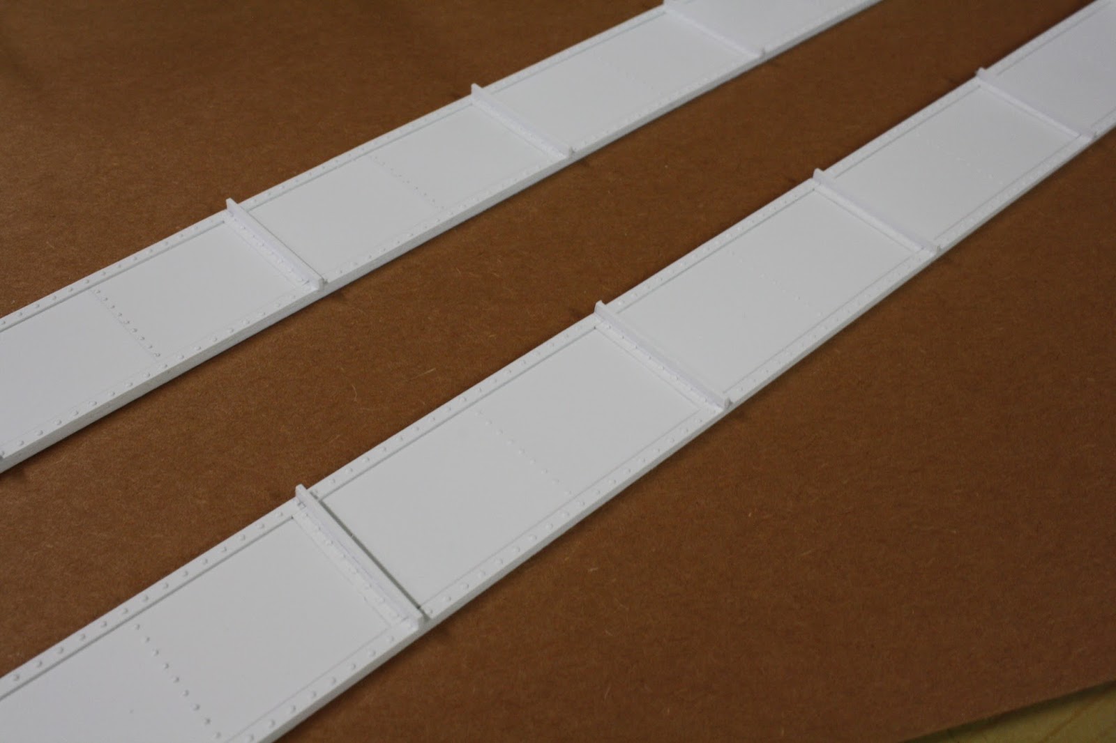
I have made a straight 12" (48 feet) section, and have modeled both sides of the girder:


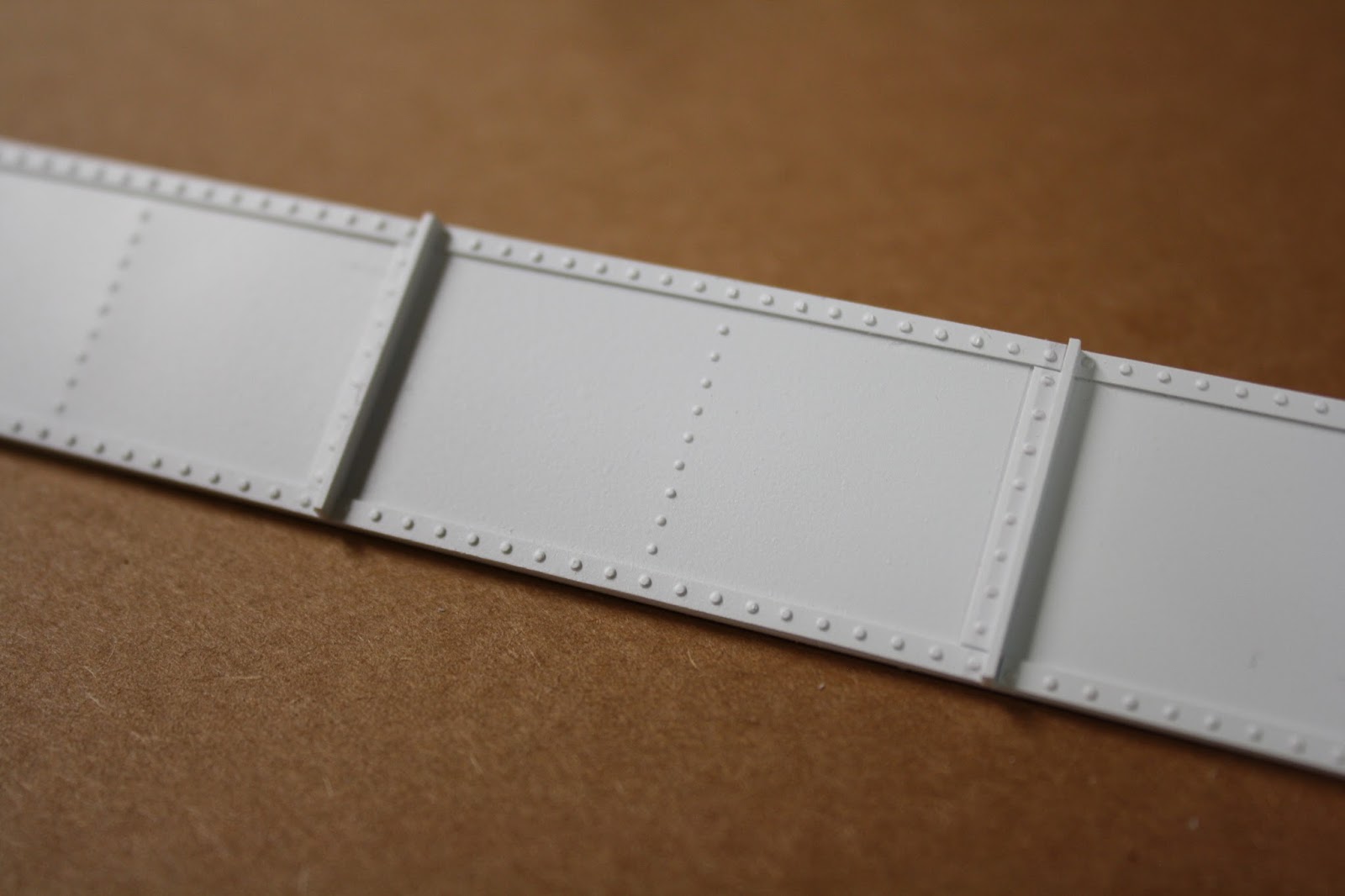
A closer view of the rivet details:


Using these two sides (front and back), I will make castings of both, and sandwich a piece of 0.080" styrene between the halves to make a girder. I will then add styrene strips to the bottom and top of the girder to make the flanges. The castings will be more decorative while the 0.080" core will make up most of the strength.

The dies, which I believe are actually for 1:43.5 or European O scale:


For the strips of rivets, the proper die is selected and placed in the metal carrier. I have made a small stryene holder to hold everything in place:


Putting in the bottom die and aligning the styrene strip (in this case 0.015" x 0.080"):


Then put the top die in place and start pressing away. The bottom die prevents the styrene from deforming, so the rivets turn out very nice.


The rivets on the web of the girder are done in a similar manner. The proper die is selected (again I made a small styrene alignment tool):


Line everything up and start punching away. Again I am using 0.015" styrene.


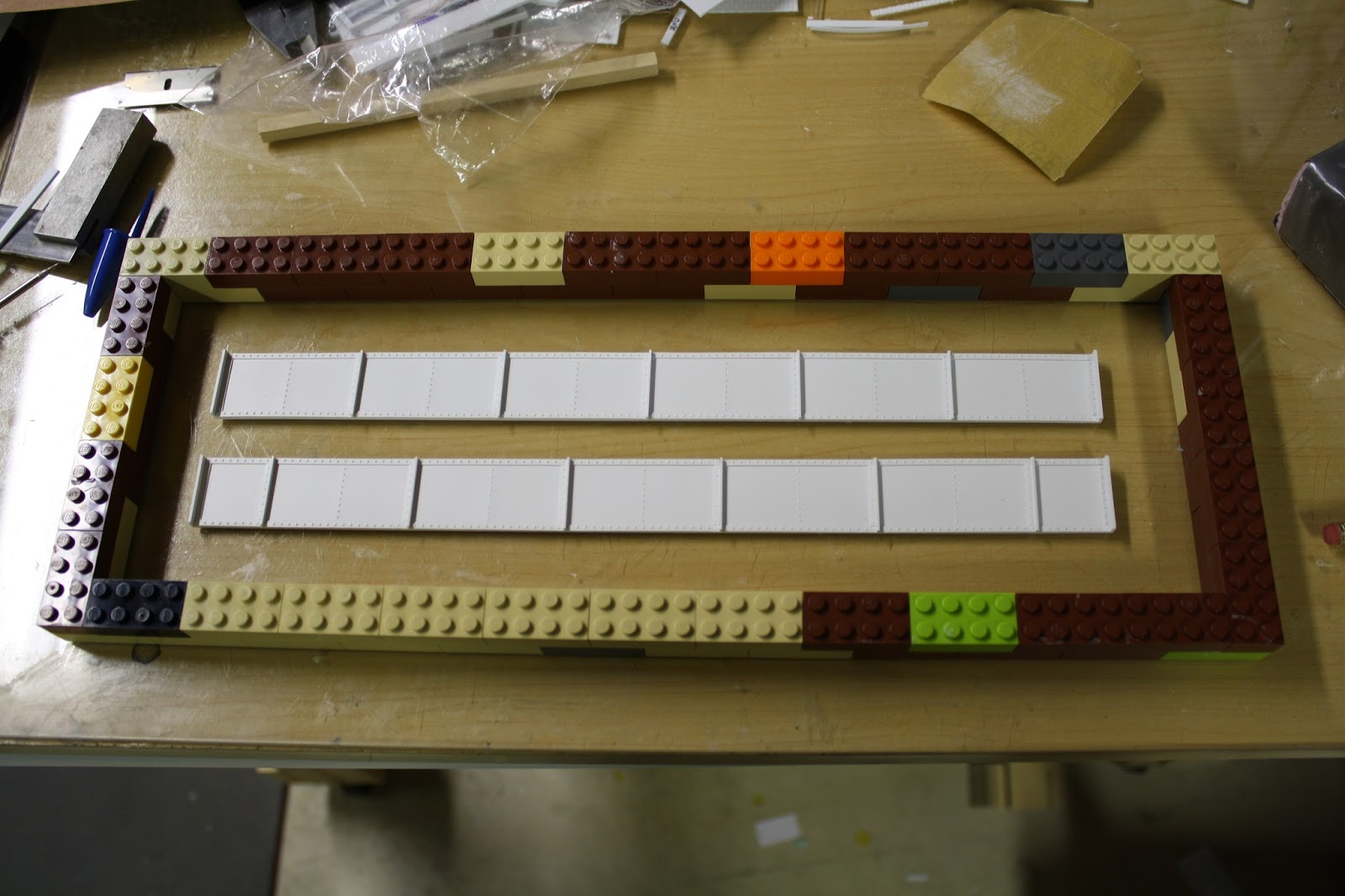
Then, after priming the girders white, I made a mold box out of borrowed Legos. I seal the Legos to my plate of glass using Vaseline, and "glue" the girders to the glass also with Vaseline. The Vaseline won't prevent the silicone mold material from completely creeping under the masters, but it'll keep them from "floating" up.


For making a mold, I use the following materials I get from Reynolds Advanced Materials. They have a store in Countryside, IL, that is conveniently on my way home from work.


I don't use a pressure vessel, so, its best efforts. The mold filled with silicone rubber:


The material sets up in about four hours, but I like to leave it sit overnight to be sure. I'll post a follow-up to see how this works. I ran low on silicone so I had to use some old stuff I had laying around...not sure how that will work.

Benchwork expansion:

I built an approximately 9' long by 30" wide shelf expansion that will eventually be a terminal of some kind on the other side of my layout / utility basement room:


I had to relocate most of my signs, but that's a small price to pay for more layout. I am also making a connection behind the hot water heater to the rest of the layout. The far left section of the benchwork is removable so I can, if ever needed, remove the hot water heater.

The signs were moved to the other side of the layout. I've also re-purposed some of my old kitchen cabinets for additional storage. In the picture above, the cabinets are underneath the new benchwork. In the below, I put a large wall cabinet on wheels so I can move it out of the way.


I've also begun mocking up the staircase to the Southport Station:


And a view down the other side of the layout, with some base cabinets, but still very messy.


Sunday, June 23, 2013

Back to the drawing board

I finally got my 4000 end back from Shapeways, and well, I need to rethink some of the design.

First off, the material comes coated in coated in a wax like substance that is VERY hard to remove and no paint will stick to. So, in the below photos, the white paint you see is about the fifth coat ... the other coats were scraped off as they never cured. So, in some areas, the paint is pretty rough/thick.

Second, the material is fragile/brittle, as you can see by the missing chunk in the lower left. OOOPS! While attempting to photograph, I dropped the piece and chipped the corner.


Overall, there was a lot more rough areas than I expected. Also, I think I put too many rivets along the sides and bottom. That made for some of the roughness. Also, the detail on the anti-climber isn't as good as my previous anti-climber sample as the two piece were printed in different directions. So, the detail in this piece isn't as "crisp" as the first anti-climber sample.

I think I might split this into two pieces .... the anti-climber and the end, with less rivets. But, some of the detail is very fine, such as the headlight assemblies. So, some areas are good, some others, not so good. I will do a re-design on Sketchup and give it another go.

Other than that, not a lot happening on the layout. Just working on small details:

I put some grass in behind the Cabrini Playlot:


Doing some minor detailing of the new buildings (window shades):


I planted some bushes around the two flat's garage:


I finally sorted out the door to my fuse panel. I took off the metal hinges and now the door is held on by magnets. So, I don't need to remove the track and structure to get at the fuses. Just slide the magnets out of the way and remove the door. As an added bonus, I can hold the door really close to read the fuse descriptions since I can barely see them anyways.


LUCKILY the home renovations are slowly coming to an end. I just have the baseboards and some minor trim to finish. So hopefully, I can get back to work on the layout full time. I might put the 4000 car on the back burner and focus on the expansion along the fuse panel wall. I've got an area to add another island station. We'll see if it can fit.

Thursday, May 16, 2013

Success in all three dimensions

Aside from home improvements (650 square feet of hardwood floor laid, 100 more to go!), I've still been experimenting with 3D modeling

I've experienced some success with making a sample of an anticlimber I hope to use on my 4000 model.

I just received the print out from Shapeways and am pleasantly happy with the results ...


This picture shows the printout next to an MTH 6000 series. I just did this as a test to see how it would turn out and experiment with rivet sizes. The rivets are 3/4" in circumference and 1/2" tall.

A closer view shows more detail:

I sprayed the part with grey automotive primer so the details would stand out. The surface appears rougher than it actually is. The dimples on the ends are guide holes I will use to drill for grab irons.

With this test successful, I'm continuing to model the rest of the car end and hope to have a completed, printed car end in about a month.